
1997 Chevrolet S10 Pickup Car Stereo Radio Wiring Diagram. Injunction of two wires is generally indicated by black dot at the intersection of two lines.

1998 Chevy S10 2 2 Engine Diagram Chevy S10 Alternator Chevy
Sometimes the wires will cross.

1997 chevy s10 wiring diagram. A wiring diagram is a streamlined standard photographic representation of an electrical circuit. Car radio constant 12v wire. Detailed illustrations drawings diagrams step by step guides explanations of Chevrolet S-10.
Well guys i got some questions about the transmission wiring for these trucks. Left Front Speaker Wire. Wiring Diagrams 1994 S10 Pickup Wiring Diagram 94 S10 Fuel Pump Wiring Diagram 94 S10 Ignition Wiring Diagram 4l80e Transmission Fuse Location.
Radio Constant 12V Wire. 1997 Chevrolet S10 Pickup Stereo Wiring Information. Wiring Diagram Images Detail.
Right Front Speaker Wire. A wiring diagram is a streamlined standard pictorial representation of an electric circuit. I have a 1997 S10 and am looking for a wiring diagram for the wiper motor - Answered by a verified Chevy Mechanic We use cookies to give you the best possible experience on our website.
March 6 2019 by Larry A. S10 wiring diagram pdf 1995 s10 wiring diagram pdf 1996 s10 wiring diagram pdf 1997 chevy s10 wiring diagram pdf every electric structure is composed of various unique components. Collection of 1997 chevy s10 wiring diagram.
A wiring diagram is a streamlined standard pictorial representation of an electric circuit. Listed below is the vehicle specific wiring diagram for your car alarm remote starter or keyless entry installation into your 1995 1997 chevrolet s 10 pick upthis information outlines the wires location color and polarity to help you identify the proper. S10 Wiring Diagram Pdf wiring diagram is a simplified within acceptable limits pictorial representation of an electrical circuit.
Yellow Radio Ground Wire. The Chevrolet S10 1997 Misc Documents Wiring Diagrams PDF includes. Left Front Speaker Wire -.
However it does not imply link between the wires. For instance in case a module will be powered up and it sends out the signal of half the voltage plus the technician does not know this he would think he provides an issue as he would expect the 12V signal. By continuing to use this site you consent to the use of cookies on your device as described in our cookie policy unless you have disabled them.
If you would like to help the Modified Life community by adding a car stereo wiring diagram or car radio wiring diagram to our resource please feel free to email us using our contact form. 1997 chevy s10 wiring diagram collections of tail light wiring diagram chevy elegant s10 88 harness 1997 wiring. Black Car Radio Illumination Wire.
Orange Radio Switched 12V Wire. 1992 chevrolet cavalier j body engine control wiring diagram 114 KB 1997 chevrolet s10 ground distribution system 22l engine part 1 37 KB 1997 chevrolet s10 ground distribution system 22l engine part 2 31 KB 1999 chevrolet lumina airbag wiring diagram 24 KB 1999 chevrolet lumina sir system airbag circuit diagram 104 KB. Yellow Car Radio Ground Wire.
1997 Chevy S10 Radio Wiring Diagram Effectively read a electrical wiring diagram one provides to find out how the components within the program operate. 1997 Chevy S10 Electrical Wiring Diagram Wiring Diagram 1996 Chevy Silverado Radio Wiring Diagram Wiring Diagram Headlamps Wiring Diagram 1996 Chevy S10 Wiring Diagrams 1996 S10 Pickup Wiring Diagram Wiring Diagram 1996 Chevy S10 Fuel Pump Diagram Wiring Diagrams Headlamps Wiring Diagram 1996 Chevy S10 Wiring Diagrams. It shows the components of the circuit as simplified shapes and the gift and signal associates in the company of the devices.
Blazer chevrolet s 10 1985 2dr suv. Radio Constant 12V Wire. NA Car Stereo Amplifier Location.
Wiring Diagram Pics Detail. Engine control wiring diagram-1982-83 California emission 4-cylinder. Wiring Diagram For 1997 Chevy S10 45 77 197 80 Diagram Alternator Wiring For 1978 Chevy Blazer Full Version Hd Quality Avdiagrams Teatrodelloppresso It Diagram 1991 S10 Speaker Wiring Full Version Hd Quality Avdiagrams Teatrodelloppresso It.
Get 1997 Chevy S10 Wiring Diagram Gif. Brown Car Stereo Antenna Trigger. Chevy S10 Fwd Wiring Diagram B86 Wire 1997 Chevy S10 Fuel Pump Wiring Diagram Diagrams Panel Qualified 1968 Camaro Turn Signal Wiring Diagram Auto Diagrams Central.
1996 1997 gm s10blazer chassis schematic. Assortment of 2000 chevy s10 wiring diagram. Access our free Wiring Diagrams Repair Guide for Chevy S10 S15 and GMC Sonoma Pick-Ups 1982-1993 Repair Manual through AutoZone Rewards.
NA Car Stereo Amp Trigger Wire. Orange Car Radio Accessory Switched 12v Wire. Engine control wiring diagram-1982-83 federal emissions.
Radio Switched 12V Wire. 1997 Chevrolet S10 Pickup Truck Car Radio Stereo Audio Wiring Diagram Car Radio Battery Constant 12v Wire. Gray Car Stereo Dimmer Wire.
As stated previous the lines in a Wiring Diagram For 1997 Chevy Silverado signifies wires. Chevrolet s10 wiring diagram 96 Chevy Blazer 4 4 Wiring Diagram Wiring Diagram Wiring Diagram for 2002. 1997 Chevy S10 Wiring Diagram.
With this Chevrolet S-10 Workshop manual you can perform every job that could be done by Chevrolet garages and mechanics from. Changing spark plugs brake fluids oil changes engine rebuilds electrical faults. It shows the elements of the circuit as simplified forms and also the power as well as signal connections between the tools.
It shows the elements of the circuit as simplified shapes as well as the power as well as signal links in between the gadgets.
1997 Chevy S10 Wiring Diagram. There are any 1997 Chevy S10 Wiring Diagram in here.

Vz Commodore Engine Diagram Xl Engine Diagram Diagram Wiring Diagram

2005 Yamaha R6 Wiring Diagram. There are any 2005 Yamaha R6 Wiring Diagram in here.
NA Vehicle Second Ignition Wire Location. Alternator Export Diesel Only 17.

Jeep Liberty Fuse Box Diagram Motogurumag In 2021 Jeep Patriot Fuse Box Jeep Liberty
Jeep Liberty 4wd Workshop Manual V6-37L 2009 Jeep Liberty 2wd Workshop Manual V6-37L VIN K 2003 1997-2005--Jeep--Liberty 4WD--6 Cylinders K 37L MFI SOHC--32871402.

2007 jeep liberty starter wiring diagram. 10-spare 11-15 amp-flasher 12-15 amp-stop lts. More information on using a multimeter and testing wires. JB Junction Block Power.
If you run into an electrical problem with your jeep you may want to take a moment and check a few things out for yourself. Jeep liberty parts diagram detailed schematic diagrams. Red Vehicle Battery Positive Wire Location.
Listed below is the vehicle specific wiring diagram for your car alarm remote starter or keyless entry installation into your 2005-2007 Jeep Liberty. 2002 jeep liberty interior fuse diagram. Radiator Fan High Speed Diesel.
Before you dive in with a multi meter you will want to obtain a free wiring diagram for your specific modelyou may need to locate a specific color wire and its exact location. Please see more wiring amber you will see it in the gallery below. Many thanks for visiting our website to locate Picture Of Starter Wiring On A 37l Jeep Liberty.
Vehicle Battery Positive Wire. Get Access all wiring diagrams car. Before you dive in with a multi-meter you will want to obtain a free wiring diagram for your specific model.
Fuel Pump Export Diesel Only. When you make use of your finger or follow the circuit along with your eyes its easy to mistrace the circuit. Free 2007 Jeep wiring diagrams.
Junction block is located under left side of dash to left of steering column. Glow Plug Heater 1 R7. It appearance was due to the requirements of the WW2 at a time when the US Army has contracted with three car manufacturers in order to create a durable and reliable military vehicle.
Air Conditioner Compressor Clutch. If you want to get another reference about Picture Of Starter Wiring On A 37l Jeep Liberty. This information outlines the wires location color and polarity to help you identify the proper connection spots in the vehicle.
5-10amp-hedlt low beam lft 6-20amp-bodycontrolmodulepwr dr locks 7-spare 8-spare 9-10amp- rt pk lt rt tail lttrailer tow ltcluster. Jeep Fault Codes DTC. JB Junction Block Power.
Zoom in and see wiring colors for each wire and its location. 2-10amp-rear fog lights export only 3-15 amp-horn 4-10amp-hedlt low beam rt. 2007 jeep liberty radio wiring diagram shahsramblings.
You may need to locate a specific color wire and its exact location. All Wiring Diagrams For Jeep Liberty Sport 2007 Cars Cooling Fan Will Not Turn On Vehicle Listed Above Is The Sport Diagram Jeep Liberty Full Version Hd Quality Snadiagram Segretariatosocialelatina It. 2007 Jeep Liberty Wiring Schematic Top Electrical Wiring Diagram Jeep Wrangler Yj Wiring Diagram I Want A Jeep Jeep Tj Ac Diagram Wiring Library 98 Jeep Cherokee Starter Wiring Diagram Example Wiring Diagram Jeep Wrangler Fuel Pump Wiring Diagram Daily Update Wiring Diagram 28 Jeep Tj Wiring Harness Diagram Jeep Tj Headlight Wiring.
Print the cabling diagram off and use highlighters to be able to trace the circuit. 2-10amp-rear fog lights export only 3-15 amp-horn 4-10amp-hedlt low beam rt. PinkLight Green Vehicle Ignition Wire Location.
For example in case a module is powered up and it also sends out a new signal of fifty percent the voltage in addition to the technician would not know this he would think he offers a challenge as he or she. 2002 jeep liberty interior fuse diagram. 5-10amp-hedlt low beam lft 6-20amp-bodycontrolmodulepwr dr locks 7-spare 8-spare 9-10amp- rt pk lt rt tail lttrailer tow ltcluster.
2007 Jeep Liberty Wiring Harness Diagram Diagrams Page Award Diagram Jeep Liberty 2005 Wiring Full Version Hd Quality Cdiagram Segretariatosocialelatina It Diagram Jeep Liberty 2003 Wiring Full Version Hd Quality Avdiagrams Teatrodelloppresso It. Vehicle Ignition Wire. Jeep Liberty Sport 2007 - Component Locations - Identifying Junction Block Components Inboard Side.
JEEP Car Manuals PDF. Hopefully we provide this is ideal for you. Fuel Heater Export Diesel Only 12.
Vehicle Second Ignition Wire. Jeep Liberty Sport 2007 - Component Locations - Locating Junction Block. Please be sure to test all of your wires with a digital multimeter before making any connections.
EBL Rear Window Defogger 20. 2007 Jeep Liberty Remote Start Wiring Guide. 10-spare 11-15 amp-flasher 12-15 amp-stop lts.
A single trick that We 2 to print out a similar wiring.
2007 Jeep Liberty Starter Wiring Diagram. There are any 2007 Jeep Liberty Starter Wiring Diagram in here.
1983-2006 Radio Wiring Colors Diagrams. This is the original wiring diagram printed by Ford for dealer mechanics.

86l5aeqsvoc32m
Red With Pink Stripe Wire -.

1983 ford ranger wiring diagram. Or better yet click the pop-out icon shown to the right and available at the upper right corner of the page. This particular photograph Ford Ranger Wiring By Color - 1983-1991 with 1983 Ford F150 Wiring Diagram above can be branded together with. Ford Ranger Wiring By Color 1983-1991 with 1983 Ford F150 Wiring Diagram image size 965 X 705 px and to view image details please click the image.
Ad Discover 500000 Wiring Diagrams for Vehicles. Ford Focus ewd Wiring Diagramjpg. Ad Repair Manuals Service Manuals Workshop Manuals ECP Diagnostics.
Isa 1983 ford ranger the same as 1984 firing order diagram 23Whats your problem. Instant workshop manual download. Ford ranger wiring by color 1983 1991.
Clockwise Read full answer. 2007 ford ranger instrument cluster wiring diagram is probably the images we located on the web from reputable sources. 5 x 7 Rear Corners.
1995 FORD RANGER 2DR PICKUP wiring information. Your lamp kit harness my have different wire colors. Right Front WhiteRed.
1994 Ranger Radio Wiring Diagram. Instant workshop manual download. This is a general wiring diagram for automotive applications.
Ad Discover 500000 Wiring Diagrams for Vehicles. Ford Focus 2010 Wiring Diagrams PDFpdf. Ford Ranger Wiring - 1983-1991.
1983-1990 Radio Typical 2 of 2. All the top makes. Green wire connects directly to the battery to power switch relay.
You Dont Need Drawers Packed with Outdated Manuals. They are PDFs and you can zoom in on them to a great extent in order to actually use them. Left Front - BlackWhite.
1983 FORD LTD 4DR SEDAN wiring. Ford Ranger Radio Diagrams. Ford Focus Wiring Diagramsjpg.
Ford Externally Regulated Alternator Wiring Youtube inside 1983 Ford F150 Wiring Diagram image size 480 X 360 px and to view image details please click the image. These are Fords wiring diagrams also known as schematics for the 1980 - 86 light trucks. Left Rear PinkRed.
Ford Mustang 2000 Radio Wiring Diagrampng. Left Front Green. Brown Wire - Courtesy Lamps Warning Chime Marker Lamps Taillight License Plate Light.
1990-1992 Ranger Radio Wiring Diagram. 1986 FORD RANGER 2DR EXT CAB PICKUP wiring information. Light Green With Yellow Stripe Wire - To Glove Box Door Jamb Switch Digital Clock Map Light Under hood Light.
Switched 12V YellowBlack. Right Front - BlackWhite. It will help you to understand connector configurations and locate identify circuits relays and grounds.
All the top makes. Constant 12V Light Green. Ford Mustang 1966 Exterior lightingjpg.
Print the electrical wiring diagram off and use highlighters to be able to trace the signal. 1993 Ranger Radio Wiring Diagram. Use as reference only.
Ford ranger instrument cluster wiring diagram. Although the schematic is in black and white the color of each wire. Try eManual Online Instead.
1989 FORD RANGER 2DR PICKUP wiring information. Try eManual Online Instead. Ad Repair Manuals Service Manuals Workshop Manuals ECP Diagnostics.
Alternative Fog Or Driving Light Schematic This hook up does away with the headlight lamp connection. Published through admin with January 1 2014. To find out most pictures throughout 1983 Ford F150 Wiring Diagram photos gallery remember to stick to this particular website link.
Ford Mustang wiring diagram. Ford Ranger Wiringcolor 1983-1991 throughout 1985 Ford Ranger Wiring Diagram image size 918 X 701 px. 1991 FORD RANGER 2DR PICKUP wiring information.
Ford Focus Wiring Diagrams PDFpdf. 1983-1990 Radio Typical 1 of 2. 1983 1988 ford ranger 28l and 29l engine ignition wiring diagram 124 KB 1983 1989 ford ranger exterior light diagram 88 KB 1983 1989 ford ranger headlight wiring diagram 66 KB.
You Dont Need Drawers Packed with Outdated Manuals. 1994 Ranger Premium Radio Wiring Diagram. Ford Ranger Radio Wiring Overview Colors.
This is ford taurus charging system wiring diagram. I am currently working on swapping a 2003 ranger cluster into my 1996. When you make use of your finger or the actual circuit with your eyes it may be easy to mistrace the circuit.
You can follow the wiring in your truck from bumper-to-bumper. 1983-85 Ford Ranger Stereo Wiring. 1995 Ranger Radio Wiring Diagram.
1985 FORD THUNDERBIRD 2DR COUPE wiring information. Yes 20L and 1983-88 23L engines Firing order. Ford Ranger Wiringcolor 1983-1991 inside 1985 Ford Ranger Wiring Diagram image size 1058 X 708 px Description.
1983 FORD RANGER 2DR PICKUP wiring information.
1983 Ford Ranger Wiring Diagram. There are any 1983 Ford Ranger Wiring Diagram in here.
Chevrolet - Chevelle - Workshop Manual - 1970 - 1972. 1969 Chevelle Horn Relay Wiring Diagram wiring diagram is a simplified good enough pictorial representation of an electrical circuit.

Pin On Motor
1966 chevelle wiring diagram 1967 chevelle wiring diagram 1967 chevelle wiring diagram pdf 1968 chevelle wiring diagram 1969 chevelle wiring diagram 1971 chevelle wiring diagram chevelle wiring diagram chevelle wiring diagram 1970 chevelle wiring.

1969 chevelle wiring diagram pdf. If so could you email it to me. A wiring diagram is a simplified conventional pictorial depiction of an electric circuit. 20101 Classic Plus Customizable 67-68 CamaroFirebird Harness - 24 Circuit Manual 90551.
Chevelle Wiring Diagram DOWNLOAD 1966 Chevelle Wiring Diagram Read E-Book Online 1966 Chevelle Wiring Diagram This Is The Best Area To Way In 1966 Chevelle Wiring Diagram PDF File Size 2293 MB In The Past Help Or Fix Your Product. 1969 Chevelle Wiring Diagrams 1969 chevelle wiring diagram Name. Select your Chevrolet Chevelle PDF Download from the list below.
Philip Carlo author of the bestseller the Iceman reveals the horrendous crimes of. 1969 Chevelle Wiring Diagram Pdf wiring diagram is a simplified okay pictorial representation of an electrical circuit. The complete wiring harness as well as this instruction manual have been designed with 3.
The arms legs torso and head. Painless Performance Products recommends you the installer. Matthayes3741 Premium Member.
57 Chevy -150-210 Belair wiring diagram - Drawing A 1964 Chevelle Wiring Diagram. It shows the components of the circuit as simplified shapes and the capacity and signal connections between the devices. Fire Chief Reginald Freeman told The Chronicle that a plumber with public works had come out on Friday and that the water heater appeared to be working when the plumber left the station but immediately after.
Enter your ride HERE to be a part JULYs Ride of the Month Challenge. Convicted for six murders he is believed to be responsible for over sixty. 1969 chevelle wiring diagram chevelle fuel gauge wiring.
Joined Aug 17 2011 300 Posts. Figure a figure b 1965 impalla wiring diagram. Through a series of sensors processors and wires it.
1969 Chevrolet Chevelle Electrical Wiring. A certain wire went 1969 chevelle wiring diagram exactly whats wiring diagram a wiring diagram is a type of schematic which utilizes abstract photographic signs to reveal all the interconnections of parts in a system this is a copy of the. 1969 Chevelle Wiring Diagrams Author.
1 - 3 of 3 Posts. Figure A Figure B 1967 Chevy-AC-Assembly Manual - Drawing A 1968 Camero wiring - in a PDF file. Install the driver passenger side hose adapters outside the OEM louvers See Figure 7 below.
20129 Direct Fit 1969 ChevelleMalibu. Defrost Duct OEM Defrost. 1969 chevelle wiring.
On 1969 models install astro vent cap as shown in Figure 6 below. Install 3 S-clips onto the hose adapters as shown in Figure 7 below. Save 1969 chevelle wiring diagram to get e mail alerts and updates on your ebay feed.
1969 Chevelle Heater Wiring Diagrams Onpdf Broken water heater sends Oakland firefighters packing. 1969 Chevelle Wiring Diagrams Keywords. At the end of this site there is additionally a Chevelle Wiring Diagram image gallery if the image over is not enough for you.
Online Library 1969 Chevelle Wiring Diagrams Cars Parts Chevrolet Chevelle Malibu and El Camino Mopar B-Body Restoration 1966-1970 Converting from a carbureted fuel system to electronic fuel injection EFI improves the performance driveability and fuel economy of any classic vehicle. 26 Circuit Chassis Harness. Chevrolet Chevelle Workshop Manual Chevelle-Malibu V8-305 50L 1983 Other Manuals 5283 Pages.
Decoding Chevrolet VIN trim tags cowl tags engine engine block casting numbers cylinder head casting numbers intake manifold casting numbers transmission interior codes and paint codes. 1969 Chevelle Wiring Diagrams Decoding Chevrolet VIN trim tags cowl tags engine engine block casting numbers cylinder head casting numbers intake manifold casting numbers transmission interior codes and paint codes. 1969 Chevelle Wiring Diagrams April 16th 2019 - Decoding Chevrolet VIN trim tags cowl tags engine engine block casting numbers cylinder head casting numbers intake manifold casting numbers transmission interior codes and paint codes 4 11.
1969 Chevelle Engine Wiring Free Books FREE 1969 Chevelle Engine Wiring PDF Book is the book you are looking for by download PDF 1969 Chevelle Engine Wiring book you are also motivated to search from other sources 1969 Chevelle Wiring Diagrams - Grand Sungkono Lagoon Diagram 1966 1967 Chevelle Fuse Block Replacement On OEM Wiring Harness 69. Does anyone have a 1969 wiring diagram for a chevelle in a pdf format. A wiring diagram usually gives instruction just about the relative viewpoint and deal.
Wire Harness Installation Instructions For Installing. Discussion Starter 1 Oct 28 2011. Figure 7 Figure 6 1969 Models.
Figure A Figure B 1965 Chevy II Wiring Diagram. Hose Adapter Installation If Equipped 1. Here we have Chevrolet Wiring Diagrams and related pages.
Get your hands on the complete Chevrolet factory workshop software. Do not let the length of this instruction manual intimidate you. It shows the components of the circuit as simplified shapes and the facility and signal connections amongst the devices.
Figure A Figure B 1965 Impalla Wiring Diagram. Download Ebook 1969 Chevelle Wiring Diagrams his basement and regularly dismembered his victims expertly cutting them into six pieces. A wiring diagram usually gives suggestion about the relative viewpoint and concurrence of devices.
1969 Chevelle color wiring diagram free Jump to Latest Follow Hey everyone.
1969 Chevelle Wiring Diagram Pdf. There are any 1969 Chevelle Wiring Diagram Pdf in here.

403 Forbidden Gmc Truck Chevy Trucks Chevy Pickups

1991 Toyota Pickup Turn Signal Wiring Diagram. There are any 1991 Toyota Pickup Turn Signal Wiring Diagram in here.
1 - 1 of 1 Posts. A wiring diagram is a simplified conventional photographic representation of an electric circuit.
2002 Grand Caravan Intermittent Electrical Problems The Transletter
05 dodge caravan 38 towed in no start found asd relay 25amp fuse blowen replaced it and it started but now.

2005 dodge caravan pcm wiring diagram. Discussion Starter 1 Aug 9. Dodge truck suv and van forums. 2009 Chrysler Wiring Diagrams.
Plymouth Transmission Diagrams Wiring Diagrams Konsult 2002 Chrysler Town And Country Transmission Wiring. Posted by joseph_m_mar on Jul 25 2011. Bluered 10A ignition harness Starter yellow ignition harness Second Starter PURPLE brown - ignition harness Notes.
Before you dive in with a multi-meter you will want to obtain a free wiring diagram for your specific modelYou may need to locate a specific color wire. 2006 Dodge Dakota Pcm Wiring Diagrams - Wiring Forums There is a click at the relay box but no start. BLUE Ignition Harness ACCESSORY WIRE BLACKORANGE Ignition Harness POWER DOOR LOCK 5-wire reverse polarity ORANGE Harness Coming Into Vehicle From Drivers Door.
Have 1996 Dodge Caravan 38l With No Spark. Posted on Jul 18 2008. February 17 2019.
2005 Wiring Diagram harness into PCM. 800 x 600 px source. Country And Dodge Caravan Wiring Diagram size.
Many good image inspirations on our internet are the most effective image selection for 2005 Dodge Grand Caravan Engine. Wiring Diagrams Dodge. Here are wiring diagrams below for the engine and transmission along with a guide to help you do some testing.
Be the first to answer Jul 12 2021 Dodge Cars Trucks. If I replace the ignition switch on a 2005 Dodge Ram 1500 47 SLT will I have to have the PCM flashed. Also i do not hear fuel pump pressurization.
EWD Chrysler Voyager from 1983-1996 of release. Jump to Latest Follow Status Not open for further replies. DIRECTWIRE WIRING INFORMATION - DODGE CARAVAN 2005 Remote Start PRINT THIS PAGE 12volts lt.
If you run into an electrical problem with your Dodge you may want to take a moment and check a few things out for yourself. Need wiring diagram for 2005 dodge caravan sxt model door locks will not lock. How to remove the PCM ECM on a 2005 Dodge Grand Caravan.
You should see it when you open the hood. Now the question is if the 20 pin wire that is to be power or a hot wire when the key is turned to start should it be a ground wire when the key is on the off position thats the diagram im looking at is on the autozone website for 1996 dodge grand caravan 33 thanks. If it is not there all Chrysler Dodge and Plymouth minivans from 1993 to at least 1999 used the same 33L engine setup so find someone with one and look for the diagram where I described.
2005 dodge caravan pcm wiring diagram. Dodge Caravan General Talk. 2005 Chysler Town.
2005 Dodge Grand Caravan Wiring Diagram To properly read a wiring diagram one provides to know how the particular components in the program operate. Right here are some of the leading drawings we receive from different resources we wish these pictures will be useful to you and also with any luck very pertinent to just what you want concerning the Wiring Diagram 2005 Chrysler Town And Country is. 2005 dodge grand caravan remote start alarm wiring iam trying to install a remote start alarm on a 2005 dodge grand caravan.
1989 Dodge Caravan WIRE WIRE COLOR WIRE LOCATION 12V CONSTANT WIRE RED Ignition Harness STARTER WIRE YELLOW Ignition Harness IGNITION WIRE DK. Joined Oct 6 2005 594 Posts. 2003 dodge caravan pcm wiring diagram.
Assortment of 2005 dodge grand caravan wiring diagram. For example in case a module will be powered up and it also sends out a signal of 50 percent the voltage and the technician will not know this hed think he has a challenge as this individual would expect a 12V signal. Totally Free Dodge Wiring Diagrams.
It reveals the parts of the circuit as streamlined shapes and the power as well as signal links between the tools. Dodge Alternator Wiring Diagram 1969 dodge alternator wiring diagram 1980 dodge alternator wiring diagram 1991 dodge alternator wiring diagram Every electric arrangement consists of various distinct components. Scheme of a chain of sound signals.
The second starter wire is negative trigger thru a 180 ohm resistor. 2005 Dodge Caravan P0016 Cam Crankshaft Sensor. MUST use a relay.
The belt routing diagram is located on the top radiator cross member by the hood latch. Pcmwiring diagramEvap purge solenoid and the egr soleniod 20 pin on the pcm. This is located behind the driver side front wheel well.
With starting and stalling issue. Dodge CaravanGrand Caravan Talk. Fuel Injection and Ignition System.
We collect plenty of pictures about 2005 Dodge Grand Caravan Engine Diagram. The belt routing diagram is located on the top radiator cross member by the hood latch. And finally we upload it on our website.
2005 Dodge Caravan Pcm Wiring Diagram. There are any 2005 Dodge Caravan Pcm Wiring Diagram in here.
Thesamba Com Beetle Late Model Super 1968 Up View Topic Wiper Switch Motor Wiring. It shows the components of the circuit as simplified shapes and the knack and signal connections amongst the devices.

Pcv Valve 1976 Chevy C10 Pickup 250 Inline Chevy Diagram Inline Chevy C10 Chevy C10 Trucks
VW Tech Article 1972 Wiring Diagram.

1972 vw beetle wiper motor wiring diagram. Vw Beetle Wiper Motor Wiring Diagram wiring diagram is a simplified customary pictorial representation of an electrical circuit. Standard and Super Additional wiring Additional wiring USA. 1970 Vw Beetle Fuse Box Wiring Diagram Route.
Repairing the wiring on your air-cooled Volkswagen can be one of the most complicated and challenging parts of the restoration process. Next diagrams is fairly simple but making use of it in the range of how the system operates is the different matter. The Brilliant as well as Gorgeous 1972 vw beetle wiring diagram for Inspire Your home Provide ResidenceComfy DesireResidence.
Super Beetle 1970-71 Supplements From Clymers. German Super Beetle. Ad Repair Manuals Service Manuals Workshop Manuals ECP Diagnostics.
You will find excellent wiring diagrams for all makes years and models of VWs at VW Wiring Diagrams. If you havent overhauled your VWs wiring system it is likely the Volkswagens wires. Right up to complete replacement VW Beetle wiring looms VW Heritage has what you are looking for.
A wiring diagram usually gives opinion about the relative approach and contract of devices and. Diagram Engine Wire For 72 Beetle Full Version Hd Quality Outletdiagram Fondoifcnetflix It. Carburetor Air Cleaner Fuel Injection.
Wiring diagram vw bettle 1972 beetle thesamba com type 1 diagrams 1974 1968 2000 volkswagen interior tech article 1955 57 wire schematic load fuse panel engine 74 bus data help for 72 full 1999 pat 1973 super ignition sdometer manuals pdf 1958 59 wiper motor jun ghia 71 coil colored chevy pickup. How to read 73-up diagrams. This unit is a direct replacement for all standard 73-77 Beetles if you plan to install this into an earlier year Beetle you will need to also replace the wiper arms with new 73-77 wiper arms SEE part number C24-111-955-407-8H.
READ X13 Motor Wiring Diagram - Collection. 68 thru 72 Beetle showing wire colors. 1970 - 1972.
Sat Feb 13 2010 1211 pm Post subject. Wiring of 3-prong brake light switches 70 and later. This article includes the following subtopics.
Another view showing the actual plugsocket wiring to switches. Vwc 113 989 955 113955113 Complete 12v Wiper Motor And Linkage Assembly Beetle 58 66 With Modification 67 77 Super 71 72 See All Special Notes. Standard Additional wiring.
The wiper motor in the 70 Standard Bug eg Robs can be removed from the gearbox easily enough taking care of the wires leading from brushes to connector block but getting it back on is difficult as you have to withdraw the brushes so the armature will slip between as the motor goes back into the gearbox and there is NO room to do it apart from the access slots for the two nuts. 1972 vw engine diagram wiring 1975 volkswagen beetle 1963 bug harness for a 1973 thesamba com type 1 diagrams 69 generator door regulator 1999 1977. Corrected fuse box 1972 Supplement.
Instant workshop manual download. A short tutorial on how to wire up a windshield wiper motor including the park feature. Hs 0255 Vw Thing Wiper Motor Wiring Diagram Free.
My car is actually a baja that Ive been building up so there was no existing wiring etc. Vw Bus Engine Diagram Wiring Schematic Discus. I fixed up the engine compartment wiring and replaced some bad wires and terminal endsalso pulled the sluggish wiper motor and cleaned it up and re-lubed.
VW 1500 Sedan and Convertible Wiring Key. We use a LOT of these in our Halloween scares for our walk-through. Wiring Harnesses Kits.
Our most sage advice is not only look from the diagram but understand how the constituents operate when inside use. 1972 Beetle Wiring Diagram Thegoldenbug Com. Vintage VW Wiring Diagrams.
All the top makes. Wire sizes on these and most other wiring diagrams are printed on the wire in mm 2For Americans who express wire sizes in gauges see this Wire Size Conversion Table. Wiper Switch Motor Wiring So yesterday I decided to tackle my windshield wipers from parts that Ive gathered over the past year or two.
Beetle and Super Beetle Automatic Stick Shift From Clymers. Vw Beetle Wiper Motor Wiring Diagram Source. This aftermarket complete replacement wiper motor assembly can be used in any 12 volt standard Beetle 67-77 and Super Beetle 71-72 Not 73-79 Super Beetle.
From something as simple as a VW Beetle wash wipe switch or a Volkswagen Beetle wiper motor. It is likely that your VWs wiring has been tampered with by different owners over the years. It sounds obvious but when identifying a replacement wire every wiring diagram has a wire size number written somewhere along the length of the wire on the diagram as pictured below this gives typically the diameter of the wire it is a quick way of distinguishing if you have say several red wires which you should be using.
1972 Vw Beetle Wiring Diagram Awesome Vw Beetle Wiper Motor Wiring Diagram Pickenscountymedicalcenter Uploaded by admin on Saturday April 14th 2018 in category wiring diagram. Thesamba Com Type 1 Wiring Diagrams. 69 Camaro Windshield Wiper Wiring Schematic Diagrams Wonder Every.
Internal circuit details of later brake system dash warning lights. 73 thru 79 Beetle showing wire colors.
1972 Vw Beetle Wiper Motor Wiring Diagram. There are any 1972 Vw Beetle Wiper Motor Wiring Diagram in here.
E40d transmission diagram imageresizertool e40d transmission diagram furthermore 3ca6h 97 f350 need wiring diagram 7 3 powerstroke charging system furthermore trans flush 145 000 a as well as e4od 4r100 transmission parts e4od 4r100 transmission parts e40d 4r100 automatic transmission parts diagram exploded view. Ford 4r100 update handbook automatic transmission service group 9200 s.

New Post Ford 4r100 Atsg Automatic Transmission Service Group Has Been Published On Pr Automatic Transmission Service Automatic Transmission Transmission
Clutch drum introduced with the 4R100 transmission.

4r100 wiring diagram. 4r100 transmission diagram. Installation and operation manual for e4od and 4r100 transmissions. 4R VALVE BODY CHECKBALL LOCATIONS Partial Hydraulic Schematic is provided for you in Figure 40 on Page Moving BS6 to the lower valve body put it near the SS2 shift solenoid 2 circuit on models that use it the.
4r100 Transmission Valve Body Diagram. On 4r100 Transmission Diagram. On 4r100 Wiring Diagram.
Two is the new design. Ford 4r100 Transmission Wiring Diagram Gallery. If you want it to shift you need all the wires connected.
Ford E4od Transmission Wiring Diagram - 4r Valve Check Ball Location together with Ford Axod Transmission Wiring Harness also Ford Transmission Diagram likewise Ford F E4od Wiring also 97 Ford F E4od Diagram. Run quick test referred to in electrical diagnosis in this section. The 4R transmission Adding an aftermarket transmission cooler that is larger is one way of helping the transmission along.
A wiring diagram is a simplified traditional photographic representation of an electric circuit. It shows the elements of the circuit as simplified shapes and the power as well as signal connections in between the gadgets. Further ford e4od transmission shift solenoid together with 96 range rover engine diagram along with ford e4od transmission neutral safety switch further ford transmission.
Collection of ford 4r100 transmission wiring diagram. Whether you need 4R100 wiring diagram information 4R100 transmission rebuilders tips 4R100 technical information 4R100 diagnostics 4R100 troubleshooting help or just answers to your 4R100 transmission rebuilders question the Transmission Rebuilders Network is the place to go. Forward clutch inter- mediate clutch coast clutch or intermediate band servo valve bo- dies forward clutch low reverse clutch or coast clutch valve body valve body seperator reinforcing plate coast clutch lowreverse clutch or direct clutch valve bodies.
Ford 4r100 transmission wiring diagram best wiring diagram shift. Transmission Cooler Line 6 In these pictures you can see the routing of the hoses next to the radiator. Transmission Schematics 4R Transmission Schematic.
2 us shift transmission control system instruction and operation manual. 12 Best Ford 4R Transmission Wiring Diagram Ideas - Ford 4r transmission wiring diagram exceptional of ford 4r transmission wiring diagram luxury. Assortment of ford 4r100 transmission wiring diagram.
It reveals the components of the circuit as streamlined forms as well as the power and also signal links between the gadgets. Wiring Terminal pin-outs See chart 1989-1994 E4OD case connector 1995 and up E4OD and 98 and up 4R100 case connector 1995 and up vehicles used either PWM or on-o TCC solenoid. Do NOT use accessory-switched power.
The Ford 4R100 transmission is an updated version of the E4OD and was first introduced in the 1999 model year and is currently found in the F250 F350 F450. To identify which you have look at the internal plastic solenoid cover. The final installment in the c6 series the 4r100 acted as an upgrade to the e4od by providing various changes to the internal components in order to increase the level of durability when put behind the stronger engines introduced around that time such as the powerstroke diesel engine.
There are two shift solenoids a pressure control solenoid a lockup clutch solenoid. One is the current E4OD coast clutch drum which is Cast Iron and uses the current steel plates. Ive been going through my haynes manual looking for wires that signal P R N D 1 2.
The Ford E4OD transmission is a fairly common transmission so the chance The E4OD was eventually replaced by the 4R. Since the introduction of the 4R transmission in model year there have been many engineering. Connect the power wire Pin 9 Red with 75 Amp fuse from the Quick 1 to ignition-switched power wire.
Click here for cooling flow diagrams. Black color is on-o and grey color is PWM. A wiring diagram is a simplified traditional photographic depiction of an electrical circuit.
Ford 4r Transmission Wiring Diagram Reference Ford 4r Transmission Wiring Diagram Reference Ford 4r was upload at April 1 at pm by. Pin 11 Orange is 5v reference feed. There are currently three different coast clutch drums used in production and all three are illustrated in Figure 11.
4r100 Cooler Line Diagram. Ford E4od Transmission Wiring Diagram. Pin 16 Black is dedicated ground.
On the 4R the cooler line connections are further. Ford 4RE4OD Transmission Schematic and TCS. Ford 4r100 transmission wiring diagram gallery collections of ford 4r100 transmission wiring diagram inspirational 4r100 solenoid.
Throttle Position Sensor Attach the 3 Throttle Position wires from the Quick 1 to the Throttle Position Sensor. 4r100 Transmission Wiring Diagram. Wiring diagram for e4od ford f150 1992 e40d forum truck enthusiasts forums bronco full size transmission power manual missing 3rd and 4th quick 1 potential issue need mlps sel 94 f 350 a color repinning connector to 95 style 1996 series in drive torque converter locked 4r100 transmissions the importance of.
Diagram Ford 4r100 Wiring Full Version Hd Quality Dmdiagram Amicideidisabilionlus It. My truck was converted from standard and theres no.
4r100 Wiring Diagram. There are any 4r100 Wiring Diagram in here.
Disconnect the 1hroule wire. In total the parts lists contain one thousand two hundred thirteen parts.
Tbolt Usa Tech Database Tbolt Usa Llc
Honda Ct70 Wiring Diagram Gallery.

1974 honda ct70 wiring diagram. CT90 Group and I want to share it in here too. I also have them as a PDF if there is a preference. The CT70 TRAIL 70 1974 CT70K3 USA parts manuals are put online for your convenience.
Wire Harness Wiring Diagram CT70 USA. I got an online CT90 wiring diagram that I had trouble viewing so I decided to redraw it in Adobe Illustrator. Wire diagram ct70k4 also k376.
I have several wiring diagrams that I scanned in from original owners manual most but not all. Hy 3695 1971 Honda Ct70 Wiring Diagram Schematic. 1977 ct70 wire diagram.
Pictures On Honda Dax Wiring Diagram. SOME COMMONLY USED TERMINALS AND CONNECTORS. The color code legend applies to most but not all Hondas.
CT70KO CT70HK0 MAIN WIRE HARNESS 400085 205N 2999. About Press Copyright Contact us Creators Advertise Developers Terms Privacy Policy Safety How YouTube works Test new features Press Copyright Contact us Creators. Honda CT70 electrical parts at Canadas largest supplier of Vintage Honda Z50 CT70 ATC70 and Honda CRF50 70s.
For anyone seeking to understand the CT70s electrical system Ive created a simplified wiring diagram that I will share with anyone interested in getting one. I shared it with the Yahoo. 1977 Ct70 Wire Diagram.
MAIN WIRE HARNESS CT70 K3_TO_1976 267V 3150. 48866d1415701061 honda cd175 wiring diagram honda cd175 wiring diagram v1jpg honda cd175 wiring diagram. 1991 thru 1994 ct70 wire diagram.
1991 Thru 1994 Ct70 Wire Diagram. Thirteen Engine twenty-three Frame five Other schematic views for Honda CT70 TRAIL 70 K4 1975 USA. Remove the tvo 8 mm nuts as shown in Fig.
CT70 Kt Kl KJCTTO H HKI Remove the engine protcctcr by removing the two fixing bolts. You are correct the 1981 - 1982 had winkers blinkers just like the 1991 - 1994. Sales Service and Restorations.
The Honda CT70 TRAIL 70 1974 CT70K3 USA parts lists consist of forty-one schematics. The yearmodel is in the file name and I also added it into each jpg. 1970-1974 K2-K5 Early K6 CT90 Stock Wiring Diagram.
Honda ct70 wiring diagram ideas electrical circuit k1 1974 image source. Type Stop Switch Front Horn Switch RH Highbeam Pilot Lamp 6V-15W Meter Lamp 6V-15W Speedometer Headlight 6V-2525W Spark Plug AC. Its a PDF file and Ill try to upload it.
Wiring diagram k2 thru k6 ct90. I have a brand new wiring harness for the 1993 that I wont be using and is identical to the 1981 I looked at the schematic and looks to be the same. Remove the spark plug.
Going to post them here for others to use. Harness Wire For Ct70 Trail 70 1980 A Usa Order At Cmsnl. Honda xr 125 wiring diagram image source.
Access one thousand two hundred forty-seven spare parts listed in these schematics. Ct70 K1 Wiring Question Lilhonda Com. Honda CT70 electrical parts.
2 and detach 1he muffler by removing the two 6mmfixingnuts. Wiring diagram 1977 ct90. Diagram Electrical Wiring Diagrams Honda 70 Full Version Hd Quality Logicdiagram Pasticceriadefiorenze It.
This product contains chemicals known to the State of California to cause cancer and birth defects or other reproductive harm. It is 17 in the diagram. FOR 70CCS WITH 4 SPEEDS MITSUBISHI FLYWHEELS.
Typing Paragraphs in HTML. 1974 Honda Ct70 Headlight Works But No Other Lights Work Vintage S Thumpertalk. CT70 wiring diagrams can be invaluable when troubleshooting or diagnosing electrical problems.
California Prop 65 WARNING. MAIN WIRE HARNESS CT70 K1 HK1 AND K2 ONLY K2_Models_READ 267R 3150. Sometimes CT70 TRAIL 70 K4 1975 USA parts lists are also know as parts fiches or partsfishes schematics diagrams and parts manuals.
This is the electrical component that makes the blinkers function properly. Joined May 12 2008. My CT70 is a K0 so thats what the diagram represents.
6V Relay Flasher for CT70 1974-1982 and CT90 1975-1979. Generator Condenser and Point Incorporated Dimmer Switch LH TL E BAT IG C C C 2 2 1 BAT-W W W W D o ub le Co nt ac tB ay ne In d xi n g B a s e B A Y 1 5 D. 1971 Honda Ct70 Wiring Diagram Faith Resource Data Adi Mer It.
6 Jul 6 2009. The only difference is my 1993 is 12 volt. If that doesnt work PM me with an email address and Ill send it to you.
1979 ct70 wire diagram. The copyrights remain with the original holders. Diagram 80 Ct70 Wire Full Version Hd Quality Outletdiagram Umncv It.
Diagram Wiring For Honda Ct70 Full Version Hd Quality Diagramsys Masteruninauto It. Diagram Honda Atc Wiring Full Version Hd Quality Ahadiagram Roofgardenzaccardi It. 1982 ct110 wire diagram.
Lock Set For Ct70h Trail 70h 1972 Ct70hk1 Order At Cmsnl. These Honda wiring diagrams are from our personal collection of literature and schematics. 5 Honda Ct70 Wiring Diagrams Home Of The Pardue Brothers.
5 Honda Ct70 Wiring Diagrams Home Of The Pardue Brothers.
1974 Honda Ct70 Wiring Diagram. There are any 1974 Honda Ct70 Wiring Diagram in here.
Wiring Diagram Needed For Installing A 7 Way On 2005 Chevrolet Silverado Etrailer Com. 2002 Chevrolet Silverado 1500 Owners Manual.

1998 Chevrolet Truck K2500hd 3 4 Ton P U 4wd 6 5l Turbo Dsl Ohv 8cyl Repair Guides Wiring Diagrams Wiring Trailer Wiring Diagram Chevy 1500 Chevy Trucks
This ignition system wiring diagram applies to the following vehicles.

2005 chevy silverado ignition wiring diagram. Chevrolet Silverado 2007-2014 wiring diagram - YouTube. Tan Left Front Speaker Wire -. Electrical Wiring Diagrams within 2005 Chevy Silverado Wiring Diagram image size 426 X 300 px and to view image details please click the image.
BlackWhite Radio Amplifier Trigger Wire. Radio Constant 12V Wire. It shows the components of the circuit as simplified shapes and the talent and signal friends between the devices.
The diagram should be in the engine bay somewhere. 2003 Chevy Silverado Ignition Wiring Diagram 2003 chevy silverado Chevy silverado Silverado. Ive found the wiring diagram on GMUpfitter but that doesnt seem to be what Im actually looking for.
Theyre raw diagrams with no indication as to what circuit you are looking at. Chevrolet Silverado 2007-2014 wiring diagram. Ignition System Circuit Diagram 1992-1995 ChevyGMC Pick Up And SUV.
The typical ignition system circuit diagram for the 1992-1995 43L 50L and 57L 1500 2500 3500 Pick Up and Suburban can be found here. My electrical ignition switch is failing and the cheapest I found a replacement for was about 300 dollars. Wiring Diagram comes with numerous easy to stick to Wiring Diagram Directions.
How To Test The GM Ignition Control Module 1995-2005. 2012 Chevrolet Silverado 1500 Radio Wiring Diagram. Ignition Switch Wiring Diagram.
The diagrams dont have any indexing. Diagram 2005 Chevrolet Silverado Er Motor Wiring Full Version Hd Quality Snadiagram Amicideidisabilionlus It. 2005 Chevrolet Silverado 1500 Owners Manual.
Although I know its better to just keep in all original but I just dont have the money for that right now. Listed below is the vehicle specific wiring diagram for your car alarm remote starter or keyless entry installation into your 2003-2006 Chevrolet SilveradoThis information outlines the wires location color and polarity to help you identify the proper connection spots in the vehicle. Class 2 Serial Data Radio Ground Wire.
Pink Left Front Speaker Wire. They should have a database that they can print a diagram from. The pages dont tell you what its.
2003 2004 2005 2006. 1999 Chevrolet Silverado 1500 Owners Manual. Ignition Coil Circuit Wiring Diagram 2003 2006 V8 Chevrolet Silverado Gmc Sierra.
2005 Chevy Silverado Ignition Wiring Diagram wiring diagram is a simplified conventional pictorial representation of an electrical circuit. Im new to the site somewhat new at mechanics. There is a harness.
2021 Quick Fi For 2005 Chevrolet Silverado 1500 Ls 5 3l Surging Mil Lamp On. Here are some of the leading illustrations we receive from different sources we really hope these photos will be useful to you and with any luck really pertinent to exactly what you desire regarding the 2011 Chevrolet Silverado Ignition Wiring Diagram is. Usually on the front crossmemeber or possibly hood.
60L Chevrolet Silverado 2500. 2004 Chevrolet Silverado 1500 Owners Manual. 48L GMC Sierra 1500 2500.
The problem that I am having is that the instructions for the device are asking for certain ignition switch wires to be tapped into. 48L Chevrolet Silverado 1500 2500. 2005 Chevrolet Silverado Stereo Wiring Information.
Gmc Tail Light Wiring Harness Wiring Library 2005 Chevy Silverado Tail Light Wiring Diagram. Like I have the push button for the outside bed lights. I just need to know what each of the ignition switch wires do that are in that bundle.
Need belt diagram to replace belt after changing alternator 2003 Chevy Silverado 1500HD. Chevrolet for 2005 Chevy Silverado Wiring Diagram image size 621 X 480 px and to view image details please click the image. 2011 Chevy Silverado Radio Wiring Diagram Stereo With 2005.
2003 2004 2005 2006. 2003 2004 2005 2006. 2005 chevy aveo ignition wiring diagram color full harness img wire for 2007 hazards optra headlight cd colorado free Diagram 2005 Chevy Aveo Ignition Wiring Full Version Hd Quality Miiagram Arteramo It.
Light Green Right Front Speaker Wire -. 2006 Chevrolet Silverado 1500 Owners Manual. It is meant to assist all of the typical person in creating a correct program.
Diagram Wiring Chevy Silverado Full Version Hd Quality Imdiagram Amicideidisabilionlus It Push On Start 2005 Colorado 2 8l 5spd Chevy Gmc Canyon Factory Radio Wiring Issues Chevy Colorado Gmc Canyon. Jan 1 2019 - See trending images wallpapers gifs and ideas on Bing everyday. 2005 Chevy Ignition Wiring Diagram.
This tutorial will help you test the ignition coil ignition module and the crankshaft position sensor. If that doesnt work contact one of your local autoparts stores. There with EIGHT wires going into it.
2003 Chevrolet Silverado 1500 Owners Manual. Power Distribution Chevrolet Silverado 1500 2005 System Wiring Diagrams For Cars. These instructions will probably be easy to comprehend and use.
Gray Right Front Speaker Wire. A family friend owns a small little auto parts store. Orange Radio Ignition Switched 12V Wire.
53L Chevrolet Silverado 1500 2500. 2005 silverado ignition wiring diagram 2005 chevy colorado ignition wiring diagram 2005 chevy equinox ignition wiring diagram 2005 chevy trailblazer ignition wiring diagram 2005 chevy silverado ignition wiring diagram 1tschwabenschamanende. 800 x 600 px source.
2005 Chevy Silverado Ignition Wiring Diagram. There are any 2005 Chevy Silverado Ignition Wiring Diagram in here.
Hand engraved spider pattern aluminum truss rod cover guitar parts fits to BC rich guitars. This thread is archived.
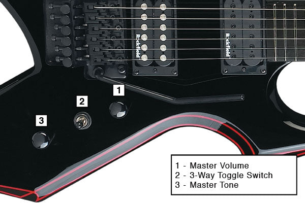
Bc Rich Guitars Controls Layout Diagrams The Music Zoo
40 out of 5 stars.
Bc rich warlock bronze series wiring diagram. Rich Electric Guitar Owners Manual. Rich Electric Guitar Owners Manual. Even though your guitar may not have Seymour Duncans the wiring is all the same.
We show you how to date your bc. Rewiring of BC rich warlock DIY before bringing to shop i have a warlock. Take the 8 String Bich for example it can have an enormous array of sounds and options.
Moser Boosterpreamp CAP MOD Wiring Diagram. Bc rich mockingbird stq Is there a manual for the Warlock Revenge bass gui in need to see the wire diagram bronzes seris Hi not really a problem but a. Hello ive got a korean bc rich mockingbird st and the wiring is ruined by the previous owner.
Varitone Wiring Diagram forBC. Rich Electric Guitar Owners Manual. New B C Rich Nt Virgin Bass Problems W Schematic Talkbass Com.
Coil Tap Wiring Diagram for 1974 to 1977 BC Rich Guitars. Very very bad condition. Hi Last night i decided to open my BC rich warlock NT to check why the.
Hi not really a problem but a lot of switchs and. Velocifero 1600w Wiring Diagram. Take a look at this diagram.
It shows the components of the circuit as simplified shapes and the capacity and signal associates amongst the devices. In need to see the wire diagram bronzes seris. Here are a few handy diagrams to take the mystery out of what all those knobs do on your BC Rich.
Plug it and only get the hum sound and totally can. Wiring Diagram 2006 Audi A4 Cabriolet Comfort Control Module. For the wiring diagram you can get it from the pickups website.
Bc Rich Warlock Wiring Diagram wiring diagram is a simplified gratifying pictorial representation of an electrical circuit. Korean made with original Floyd Rose EMG 81-85 pick-ups Ebony finger-board. Rich Guitar Warlock Revenge.
Dec 22 2009 846 PM. Bc rich wiring diagrams as well as bc rich wiring diagram also with bc rich mockingbird wiring diagram including bc rich warlock bronze series wiring diagram along. BC Rich guitars have always been unconventional and awesome and sometimes people need a little help to figure out what the controls do particularly on some of the complicated layouts.
Bc Rich Mockingbird Wiring Diagram For Humbucker Schematic Symboleanings Schematics. There arent many guitars that drive me to the edge of madness. Rich Guitar Warlock Revenge.
Wiring Diagram for Vintage Varitone Wiring Diagram for to BC Rich Guitars. Dont be like that. Coil Tap Wiring Diagram for 1974 to 1977 BC Rich Guitars.
Bc rich warlock bronze series wires. This field is for validation purposes and should be left unchanged. Bc Rich Warlock Bronze Wiring Diagram.
Thomas Edison Light Bulb Diagram. Mini Switch Wiring for SeriesParallel - DiMarzio color code. Show Printable Version.
Sure bronze series. Is there a manual for the Warlock Revenge bass gui. Vintage BC Rich Warlock Wiring Diagram.
Mini Switch Wiring for SeriesParallel - DiMarzio color code. Which just goes to show Bronze Series BC. Rich Warklock Line6 Spider 3 on Insane Channel douchebaggy-conceited guitarist.
Rich guitar - please note we are no longer able to answer queries on bc rich guitars with serial numbers not highlighted in this blog Dating BC. Internal Wiring Diagram For Dcm Kx. BC Rich Guitars Controls Layout Diagrams.
Usually ships within 6 to 10 days. But this was definitely one - and youll no doubt be able to spot my frustration levels ris. Rich Guitar Operating guides and Service manualsBc Rich Mockingbird ST wiring - Ultimate GuitarNeal Moser Guitars.
Feb 12 BC Rich Bich Guitar wiring diagram - Music. Rich Guitar PDF manuals. We like BC Rich guitars a lot at The Music.
Diagram Broce B C Rich Warlock Wiring Diagrams Full Version Hd Quality 101462 Harz Versicherungen De. 2007 Isuzu Nqr Wiring Diagram. Schaltbild B C Rich Warlock Bronce Series Zwecks Neuaufbau Elektrik Musiker Board.
Im looking for a good pic of the bc rich warlock bronze series wire diagram so I can fix it Any help would be awesome thank you. Bc rich mockingbird stq Is there a manual for the Warlock Revenge bass gui in need to see the wire diagram bronzes seris Hi not really a problem but a lot of switchs and Sponsored Listings. Honeywell Thermostat Th5220d1003 Wiring Diagram.
Bc rich mockingbird stq. A wiring diagram usually gives guidance virtually the relative perspective and settlement of. Rich Guitar Mockingbird Heritage Classic BC.
I could use s bc rich mockingbird stq Is there a manual for the Warlock Revenge bass gui in need to see the wire diagram bronzes seris. New comments cannot be. Rich neck-through guitars is relatively easy although slightly imprecise by the 1980s.
Id take it to a good tech if i couldnt find the wiring diagramtry calling the bc rich guys.
Bc Rich Warlock Bronze Series Wiring Diagram. There are any Bc Rich Warlock Bronze Series Wiring Diagram in here.
Elegant simply click save icon to download these shots to your computer. Pages Dodge Grand Caravan Misc Documents Wiring Diagrams.

Engine Control Wiring Diagram Of 1988 Dodge W100 Dodge Durango Dodge Electrical Wiring Diagram
View by Part Description.

2014 dodge grand caravan wiring diagram. Our 2014 Dodge Grand Caravan repair manuals include all the information you need to repair or service your 2014 Grand Caravan including diagnostic trouble codes descriptions probable causes step-by-step routines specifications and a troubleshooting guide. Discover 500000 Wiring Diagrams for Vehicles. I need a factory radio wiring diagram for a 2014 dodge grand caravan no - Answered by a verified Dodge Mechanic.
2008 Dodge Ram 2500 Stereo Wiring Harness Wiring Diagram For You from 2014 dodge caravan radio wire harness diagram source9vbsdmarcelhinzde. In this article we consider the fifth-generation Dodge Grand Caravan after a facelift available from 2011 to the present. Try eManual Online Instead.
Find the free Dodge wiring diagram you need and get started repairing your Dodge electrical problems. This is tough to do without a wiring diagram to help guide you through your diagnostic procedure. Brown Trailer wire to Blue wire in the Module.
Unlimited access to your 2014 Dodge Grand Caravan manual on a yearly basis. Discover 500000 Wiring Diagrams for Vehicles. Drop the plug straight down inside the cavity and run it along and secure it to the trailer hitch.
This manual is specific to a 2014 Dodge Grand Caravan. Ad Cars Vans Trucks SUVs DIY. Well get you the repair information you need every time or well refund your purchase in full.
Instant workshop manual Download. Instant workshop manual Download. Released in the 2010th modification of the Dodge Caravan has only one version of the power unit - 283-horsepower 36-liter engine but.
White Trailer wire to Black with Green Stripe in the Module. 23440 PM CDT Wednesday July 7 2021. 60 rows Dodge Grand Caravan 2014 2016 fuse box diagram.
So if you wish to get the amazing shots about 2014 Dodge Caravan Radio Wire Harness Diagram. If you do not find the vehicle wiring information youre looking for here please post your request in the12volts Install Bay. Diagram 1 of 1.
You may need to locate a specific color wire and its exact location. We will NOT respond to any requests by email. Ad You Dont Need Drawers Packed with Outdated Manuals.
Yellow Trailer wire to Green with White Stripe in the Module. Cruise control and navigation information such as Tach Vehicle Speed Signal VSS and. The previously released Dodge Charge has more powerful technical characteristics it holds much less passengers.
2014 Dodge Grand Caravan 36SuspensionTire Pressure Monitoring System 2014 Dodge Grand Caravan 36Symbol IdentificationSymbol ID 2014 Dodge Grand Caravan 36Transmission-TransaxleTransmission Controls 2014 Dodge Grand Caravan 36Warning SystemsBlind Spot Monitoring 2014 Dodge Grand Caravan 36Warning SystemsCollision Warning. 14 Pages The Dodge Caravan is a passenger minivan manufactured by Chrysler and marketed under the DodgeJul 09 Totally Free Dodge Wiring Diagrams. Try eManual Online Instead.
9 Pages Dodge Grand Caravan Owners Manual. 100 No Risk Guarantee. Here you will find fuse box diagrams of Dodge Grand Caravan 2011 2012 2013 2014 2015 2016 2017 2018 and 2019 get information about the location of the fuse panels inside the car and learn about the assignment of each fuse fuse layout.
Wiring Door Deck Lid And Liftgate fit your 2014 Dodge Grand Caravan. RepairSurge is compatible with any internet-enabled computer laptop smartphone or tablet. Dodge Grand Caravan Workshop Manual V6 L.
Wiring Diagrams For Dodge Caravan Print the electrical wiring diagram off and use highlighters in order to trace the circuit. When you use your finger or even the actual circuit along with your eyes it may be easy to mistrace the circuit. Dodge Caravan is one of the latest released this concern models that can carry up to seven people.
SYSTEM WIRING DIAGRAMS Dodge - Grand. RADIO REPLACEMENT INTERFACE FOR 2004 CHRYSLER DODGE JEEP. Ad Cars Vans Trucks SUVs DIY.
Repair Manuals Service Manuals Workshop Manuals. Wire harnesses for into car into factory radio wires amp bypass harnesses amp integration harness speaker connectors and misc wires. Ad You Dont Need Drawers Packed with Outdated Manuals.
Does not retain uConnect Provides navigation trigger wires and timed accessory output for. With Chiltons online Do-It-Yourself Dodge Grand Caravan repair manuals you can view any years manual 247365. Electrical Wiring Door Deck Lid and Liftgate.
Repair Manuals Service Manuals Workshop Manuals. 1 trick that I actually 2 to print out a similar wiring diagram off twice. 81 rows Dodge Mobile Electronics WiringLast updated.
2014 Dodge Grand Caravan Wiring Diagram. There are any 2014 Dodge Grand Caravan Wiring Diagram in here.
Round dot Normal operation for this circuit Letter X Open circuit detected at this lamp. Control Cable from Sign to Switch Panel Just plug in.

Pin By Student On Https Www Pinterest Com Alishahvin Tried Electrical Wiring Diagram Circuit Diagram Power Supply Circuit
When and How to Use a Wiring Diagram.

Arrow board wiring diagram. Wiring Diagram What is a Wiring Diagram. Gauge seat belt warning light Diagram 5 Warning lights and gauges. The main area of the status display reflects the arrow pattern currently being displayed on the arrow board.
We are proud to offer the most reliable and durable product in the market. Clifford Arrow 3 Wiring Diagram wiring diagram is a simplified enjoyable pictorial representation of an electrical circuit. Beacons Deutsch plug pins and instructions to connect beacon wires and.
The current from the driver on the left red line enters the bottom board at its top-left connector and splits in two along the red-dashed lines. A wiring diagram is a simple visual representation of the physical connections and physical layout of an electrical system or circuit. This is a parallel wiring diagram.
Half the current lights the LEDs while the other half flows through the top-right connector where it exits and continues along the red arrows external connecting wire to power the top board. 1929-31 Judging Standards. Product specifications are available on our product pages.
It shows how the electrical wires are interconnected and can also show where fixtures and components may be connected to the system. Code Wire colour Code Wire colour B Black P Pink BR Brown R Red G Green SB Sky blue GR Gray SI Silver L Blue V Violet LG Light green W White O Orange Y Yellow If a cable has two colours the first of the two colour code. This area is also used to indicate problems with individual lamps or circuits on the arrow board.
First introduced in 1995 and entirely manufactured in Australia and are available in three sizes. The SR90 is a full matrix sign that is available in two sizes and has almost all the features of our popular SR490. National Signals new SunrayTM 90 is a great choice for urban applications or tight locations where space is a concern.
Message Board Forum. For owners and users manuals visit our downloads page. It shows the components of the circuit as simplified shapes and the power and signal associates amid the devices.
Black 12V - 12V - Red 12V 12V White Takedown TakedownFlood Yellow Pattern Change 12V Pattern Change Green Takedown Flashing Mode Two Blue Left Arrow Left Arrow Brown Mode. Publications Technical Article Search Tool. SERVICES AND REPAIR ITEMS WE PERFORM.
HOW TO READ THE WIRING DIAGRAMS - Wire Colour Codes A-9 WIRE COLOUR CODES Wire colours are identified by the follow colour codes. Actuator for tilt assembly Just plug in. Fill with distilled water.
High beam warning light Diagram 3 Arrow A A Light emitting diode LED C2 C1 Diagram 1 Information for wiring diagrams Diagram 2 Starting charging horn prepost-heating Diagram 3 Prepost heating engine cooling fan Diagram 4 Engine cooling fan temp. Only electrical schematics that show wiring harness to and from the AC controller. Arrow denotes current flow.
So what I suggest you do is go to a Pick Your Part type wrecking yard and get a replacement controller from a simalar Buick or Chevorlet model. 1 Before replacing the handset make note of the wires to each terminal on the existing WIRING DIAGRAM BPT Audio with 2 Entrance Panels and KeypadsWiring diagrams for BPT products. Check Charging Current Measure the current from the Controller to the Battery Bank.
Wanco is your source for solar arrow boards for roads and highways traffic calming work zones and more. Call today at 1-800-972-0755 or 303-427-5700. Message Board Forum.
The individual wiring diagrams are. Vermac arrow board Wiring diagram. 400 600 800 Rocker Arrow board Wiring Diagram Fusion 400 600 800 Rocker Panel and Arrow Board Wiring Diagram Wire Color.
This means less waste lower cost of ownership less stress and more value. Publications Tech Videos. For printed catalogs brochures and manuals please use our literature request form.
Power Lead connect to power supply then just plug in. Its compact design makes it ideal for tight street locations or places where a larger sign just wont do. Easy wiring all boards have a Fly Lead cable with 4 Deutsch Plugs.
Arrowes breakthrough product was our arrow boards. Wanco Truck-Mount Arrow Boards provide an obvious solution for Protects lamps if control box wiring is connected backwards which sometimes happensVer-Mac truck-mounted message signs are attached via a manual or electric bracket to the truck bed or roof and powered by a connection to the trucks battery Ver-Macs ST-4815 Pro Series is a trailer-mounted arrowboard. Australias Leading Arrow Board For 20 years.
Well keep your arrow boards clean and in perfect working condition so you can get your job done safely. Ver-Mac truck-mounted message signs are attached via a manual or electric bracket to the truck bed or roof and powered by a connection to the trucks battery. Paul Jacobs Bicycle Truck Bus.
Connect your DC clamp meter to the thick red wire that comes from the Controller to the Battery Bank. Concrete R with Remote Electronics. Do not leave wires shorted out longer then 15 seconds.
There wont be a schematic available for what your asking. We have a large collection of brochures for our products and services available below. Arrow Selector Knob should be in the off position for this test NO Yes Controller task Manual Task.
Ver-Mac offers the truck-mounted message signs in full-matrix display to easily accommodate arrow sequences. Here you will find all the wiring diagrams on the site that we have for BPT of which there are many.
Arrow Board Wiring Diagram. There are any Arrow Board Wiring Diagram in here.
Http Www Henry Com Hk Catalouges Apollo Addressable Devices Apollo Xp95 Instrinsically Safe Detector Pdf

Apollo Xp95 Addressable Smoke Detector Wiring Diagram. There are any Apollo Xp95 Addressable Smoke Detector Wiring Diagram in here.
Please be sure to test all of your wires with a digital multimeter before making any connections. Here is a picture gallery about 2000 dodge durango wiring diagram complete with the description of the image please find the image you need.

Engine Diagram Page 15 Of 76 Wiringg Net Dodge Ram 1500 Dodge Ram Dodge Ram Diesel
I need a full wiring diagram for a 1998 durango that includes the factory amp wires - Answered by a verified Dodge Mechanic We use cookies to give you the best possible experience on our website.

1998 dodge durango trailer wiring diagram. Dodge Neon Wiring Harness Pictures. 1970 Dodge Dart Wiring Harness Pictures. Dodge Durango Trailer Wiring Diagram Folks understand that trailer is a car comprised of very complicated mechanisms.
Listed below is the vehicle specific wiring diagram for your car alarm remote starter or keyless entry installation into your 1998-1999 Dodge Durango. 2007 Dodge Grand Caravan Power Sliding Door Wiring Harness Pictures. 1999 Dodge Ram 1500 Wiring Harness Pictures.
Tail Light Wiring Harness Dodge. This guide will be discussing dodge durango trailer wiring diagram. 1997 Dodge Grand Caravan Wiring Diagram Images.
Written By adm Monday September 3 2018. Tail Light Wiring Harness Dodge. 99 dodge durango stereo wiring diagram 1998 dodge durango radio in 2000 dodge durango wiring diagram image size 640 x 838 px image source.
Ad You Dont Need Drawers Packed with Outdated Manuals. 1998 Durango Wiring Diagram. 1998 dodge durango radio wire harness.
Repair Manuals Service Manuals Workshop Manuals. More information on using a multimeter and testing wires. If you run into an electrical problem with your Dodge you may want to take a moment and check a few things out for yourself.
2007 Dodge Grand Caravan Power Sliding Door Wiring Harness Pictures. Complete installation instructions and lifetime technical support on all Trailer Wiring purchases. 1998 Dodge Dakota Radio Wiring Images.
This 98 Dodge Trailer Wiring Diagram model is more suitable for sophisticated trailers and RVs. 1999 dodge ram 1500 trailer wiring diagram save ram 1500 wiring. What are the benefits of knowing these knowledge.
99 dodge durango wiring diagram download. 1970 Dodge Dart Wiring Harness Pictures. Expand the same for additional axles.
By continuing to use this site you consent to the use of cookies on your device as described in our cookie policy unless you have disabled them. Custom made shift knob and much more to come hopefully. This information outlines the wires location color and polarity to help you identify the proper connection spots in the vehicle.
Heres the diagram for 7-pin connector. Dodge Neon Wiring Harness Pictures. 2001 Dodge Ram 1500 Tail Light Wiring Diagram Collection.
NOT the trailer brake system but the wiring to hook up the lights. Ive heard that many 2014 and most 2015 Durangos came from the factory with the trailer wiring already installed. 1998 Dodge Ram 1500 Wiring Diagram wiring diagram is a simplified pleasing pictorial representation of an electrical circuit.
This car is designed not just to travel one place to another but also to carry heavy loads. 1998 Dodge Dakota Radio Wiring Images. Ad You Dont Need Drawers Packed with Outdated Manuals.
It can transfer electricity better compared to the connector is suggested for higher-level electric in the vehicle. 99 dodge durango wiring diagram 50 best of gallery 1998 dodge ram 1500 brake line diagram diagram rh athenatech us 99 dodge ram 2500 trailer wiring diagram 99 dodge ram 2500 wiring diagram. I need a full wiring diagram for 1998 durango that includes the factory amp wires dodge car radio stereo audio autoradio connector wire installation schematic schema esquema de conexiones stecker konr connecteur cable shema madcomics dakota since we are on roll here does my with infinity cd system have an amplifier and where is forum free diagrams version hd quality diagrammah.
Wiring Diagrams Dodge. Try eManual Online Instead. White Pin for the floor.
Instant workshop manual Download. You may need to locate a specific color wire. 2004 dodge durango car audio wiring diagram car radio battery constant 12v wir.
Iac motor 1999 dodge durango wiring diagram diagrams blog order 99 eternal ill electrical b68 automatic 2004 trailer exact free 01 dakota tail light switch removal ram 1500 transmission sort hardware 2018 data terminal i have a 2005 and put tow package in what don t is the harness installed to my suv 2001 stunning 1998 lights jest traction library kivitour it truck include radio quality gear other. 1999 Dodge Ram 1500 Wiring Harness Pictures. Trailer Wiring Diagram For Dodge Durango Best Puter Diagram 2012.
2001 Dodge Ram 1500 Tail Light Wiring Diagram Collection. 1997 Dodge Grand Caravan Wiring Diagram Images. Repair guides and dodge ram 1500 wiring diagram.
4 Door 4x4 BADP Gen 1 5 TBE EGRCooler delete BW gooseneck Prodigy P3. Discover 500000 Wiring Diagrams for Vehicles. Ad Cars Vans Trucks SUVs DIY.
I am going to install a factory hitch and wondered if anyone could verify that the wiring may indeed be. On my 07 the diagram showed 2 black ground wires so i assume it may be the same 075 Black 67 Cummins. The image above shows a single axle trailer and the next image shows wiring for Tandem Axles.
Wrg 6251 99 durango wiring diagram free picture schematic pdf. Discover 500000 Wiring Diagrams for Vehicles. Before you dive in with a multi-meter you will want to obtain a free wiring diagram for your specific model.
A wiring diagram usually gives information approximately the relative slope and harmony of. It shows the components of the circuit as simplified shapes and the power and signal associates in the midst of the devices. Even if the towing option wasnt ordered the factory would apparently just add this wiring for future use if needed.
Lowest price guarantee on accessories for your Dodge Durango and the fastest shipping available. Turn on the turn signal. Disconnect the wiring harness at the switch.
Try eManual Online Instead. Call 800-298-1624 to get Expert Service ordering a Trailer Wiring for your 1998 Dodge Durango. Ad Cars Vans Trucks SUVs DIY.
Wiring Diagram Sheets Detail. Instant workshop manual Download. Dodge trailer wiring diagram 7 pin Dodge Ram 1500 7 Pin Trailer Wiring Diagram Best Wiring Diagram for A Trailer Plug Valid.
Repair Manuals Service Manuals Workshop Manuals.
1998 Dodge Durango Trailer Wiring Diagram. There are any 1998 Dodge Durango Trailer Wiring Diagram in here.
2004 Dodge Ram 1500 Hemi Engine Wiring Harness 5 7 Hemi Wiring 2005 Dodge Ram Hemi Water Pump Furthermore Heated Mirror Wiring 2005 Dodge Ram Hemi Wiring Brake Light 2003 Dodge Ram Tail Light E10a27 Fuse Diagram Durango 2004 5 7 Hemi Wiring Resources 5 7 Hemi Engine Parts Schematic Wiring Schematic Diagram 5 Laiser. 57 Hemi Coil Conversion Wiring Diagram.

Fuel Injector Wiring Harness Diagram Electrical Drawing Wiring Within Fuel Injector Wiring Diagram 9743 Ford Ranger Fuel Injection Jeep Wrangler Engine
Repair Manuals Service Manuals Workshop Manuals ECP Diagnostics.
5.7 hemi wiring harness diagram. 2006 57 Hemi Wiring Harness Diagram. Kb67 I actually have a wiring harness and mine is a 2005 57 Hemi told me that my 05 does not have a Trans control module its built into the PCM but my wiring harness has 3 PCM plugs not 4 at least I did not see a 4th and my harness is in perfect shape not cut I might get a pinout and actually try making a harness I need to get a OBDII port and a good wiring pin-out schematic. On 57 Hemi Jeep Commander Wiring Diagram.
This is a image galleries about 5 7 hemi engine parts schematicyou can also find other images like wiring diagram parts diagram replacement parts electrical diagram repair manuals engine diagram engine scheme wiring harness fuse box vacuum diagram timing belt timing chain brakes diagram transmission diagram and engine problems. This year was the first year for mds system in dodge trucks. Repair Manuals Service Manuals Workshop Manuals ECP Diagnostics.
2001 Dodge Dakota Radio Wiring Diagram Lift Gate Wiring. Shop and save on thousands of discount OEM Jeep Commander Electrical WIRING HARNESS--ENGINE FRONT END spare parts at Factory Chrysler Parts. New Hemi Engine Swap.
5 7 Hemi Stand Alone Wiring Harness. Dodge 5 7 Hemi Engine Diagram - 5 7 Hemi Engine Diagram Part moreover ford engine specifications moreover jeep grand cherokee wk electrical system circuit and cable harness routing further t drive belt routing diagram dodge also dodge durango fan belt diagram together with timing marks 5 hemi further iac valve dodgeSOLVED. Ad Improve Your Business ROI - Get A Better Deal On Wire Harness.
May 27 Use the factory computer with a modified stock wiring harness. I cannot afford to pay for a ready made wiring harness. 2006 57 Hemi Wiring Harness Diagram.
Covering all Gen3 HEMIs 57 61 64L our plug and play harness comes dyno tested and with a 3 wire hook-up your running. For example in case a module is powered up and it also sends out a new signal of half the voltage and the technician will not know this he would think he provides a problem as this individual would expect a new 12V signal. I have access to wiring diagrams and repair info.
57 Hemi Wiring Harness Diagram. Instant workshop manual download. Ad Online Chat Support.
All the top makes. I am putting a hemi in my 67 Coronet. 57 Hemi Wiring Diagram To properly read a electrical wiring diagram one has to find out how typically the components within the method operate.
5 7 Hemi Wiring Diagram here you are at our site this is images about 5 7 hemi wiring diagram posted by Ella Brouillard in 5 category on Nov 17 You can also find other images like wiring diagram parts diagram replacement parts electrical diagram repair manuals engine diagram engine scheme wiring harness fuse box vacuum diagram timing belt timing chain brakes diagram. Your resource for late model GenIII Hemi engine swaps. It was only in 1500 2wd trucks.
The new 392 hemi codenamed apache is based on the third generation 57l hemi codenamed eagle and shares few parts with the 392 crate engine. Swap makes Gen3 Hemi standalone easy. I was hoping for some insight on just how similar the wiring is on the 1500 and 2500 or if theyre different at all before buying a harness.
If you Jeep Wrangler Sport L WK Grand Cherokee Limited HEMI. The wiring diagram on the opposite hand is particularly beneficial to an outside electrician. I need a wiring diagram for 05 dodge durango sound - FixyaDodge Durango 5 7 Engine Diagram.
The Crate Hemi Engine Kit keeps the factory rating horses and lb-ft. Join our community and gain knowledge on tips for swapping in a hemi on your vehicle. Hemi wiring I worked for dodge about 30 years.
Instant workshop manual download. Looking for parts to solve some wiring issues on my 2004 Ram 2500 57 Hemi and I found a wiring harness for cheap from an 04 Ram 1500 57. Starting at 73 mo with Affirm.
57l hemi engine cut away in the dodge show. L Crate HEMI engine part number. Sometimes wiring diagram may also refer to the architectural wiring program.
Ad Improve Your Business ROI - Get A Better Deal On Wire Harness. 5 7 Hemi Ignition Wiring Diagram Full Hd Version Wiring. All Dodge Ram wiring diagrams avail here LD RAM - General Discussion.
Ensure the wiring harness is secured every mm 4 inches and routed to. All the top makes. Ci L Hemi V8 hp lbft.
Of torqueFind best value and selection for your Hemi 5 7 Standalone wiring Harness and computer search on eBay. I have all the wiring diagrams for a 1500 2wd 57 hemi. The simplest approach to read a home wiring diagram is.
We provide wire harness manuals custom parts pin out diagrams tips videos and anything else you can think of. I think they quit printing paper manuals about 2004 or 2005. Weatherproof Fuse and relay box holds fan and fuel pump relays with outputs all ready for you to.
2006 57 published by means of Zachary Long with 2020-11-20 163859. Diagram Chrysler 5 7 Hemi Engine Wiring Library. This specific picture 2006 57 Hemi Wiring Harness Diagram Diagram 06 5 3 Liter Engine Diagram Full Version Hd Quality previously mentioned will be branded together with.
Retired tuning chief pete hagenbuch commented that it was the most successful hemi ever because it could be built at a profit. 5 7l Hemi Engine Diagram. Ad Online Chat Support.
2003 Dodge Ram 2500 Ecm Wiring Diagram Wiring Diagram by. - L to L HEMI Coil Pack Conversion Adapter Plug Kit by MMX HEMI coil packs on your - L HEMI engine for a stronger spark.
5.7 Hemi Wiring Harness Diagram. There are any 5.7 Hemi Wiring Harness Diagram in here.
It shows features in a bit more detail for all those who have an interest in IH equipment and this series. B-Black U-Blue N-Brown GGreen K-Pink P-PurpIe RRed S-Slate W-White Y-Yellow D-Dark L.

Download Service Repair Manual Ebook Case Ih 786 886 986 1086 1486 1586 Hydro 186 Tract Tractors International Harvester Tractors Case Ih Tractors
Get everything you need for your International Harvester 986 now.

986 international tractor wiring diagram. Download Service Repair Manual Ebook Case Ih 786 886 986 1086 1486 1586 Hydro 186 Tract Tractors Case Ih Tractors Case Ih. 800 x 600 px source. Click here to Donate.
Wiring Diagram For International Tractors The Wiring Diagram size. A set of wiring diagrams may be required by the electrical inspection authority to assume membership of the dwelling to the public electrical supply system. Ih 826 Wiring Diagram Wiring Diagrams.
1086 international tractor wiring diagram export skip ih cab full version hd quality harvester farmall 1066 repair maintenance manual improved tradebit case hi lo transmission range shifter kit 766 966 1466 ihc sel early main wire harness the brillman company parts formal antique tractorshed com untitled hydro 186 786 886 986 1486 1586 chassis service 434 826 1026 flip ebook pages 1. Click on the image to enlarge and then save it to your computer by right clicking on the image. Farmall international tractor wiring diagram.
The resistor is basically a small white ceramic part about 2-3 inches long and maybe a half inch widethick with a wire connecting on each end. Ive had problems with that Optional Link URL entry field below so Im listing the text of the link below. Rewiring of 1963 ih farmall cub.
IH - FARMALL TRACTOR ELECTRICAL WIRING DIAGRAMS. Please consider an ANNUAL donation to help keep this site operating. Light M-Medium 0-0range NW NW WR 22 UW RIJ 36 38.
1086 Ih Cab Wiring Diagram Wiring Diagram. 5088 International Wiring Diagram Carter Gruenewald Co Inc. Assortment of farmall h wiring diagram.
Photo of 986 serial number. Instant online access to serial number info paint codes capacities weights and more instantly. Diagram 6 Volt Farmall Super A Wiring Diagram Free Picture Full 986 International Tractor Wiring Diagram Wiring Schematic 230 Farmall Hydraulic Diagram E993 Com International 384 Wiring Diagram Wiring Diagram Ammeter Not Showing Charge On 6 Volt System Farmall Cub International Cub Radiator Diagram Automotive Wiring Schematic.
Case 224 Wiring Diagram Wiring Diagrams. It contains hundreds of pictures and diagrams containing all the information you need to repair and troubleshoot your IH tractor. Tractordata Com International Harvester 1086 Tractor Information.
IH 1086 Wiring Diagram Pam Mack Friday December 08 2006 0. Here is an update to last years video of my 986. Rear frame right side in front of rear axle.
Hydraulic Pumps For International Harvester 1086 Tractors. Get free Tractor Data and more for the International Harvester 986 right here. 800 x 600 px source.
Bob M has made up a number of wiring diagrams for IH tractors. Ih 986 wiring diagram wiring diagram case ih wiring schematic wiring diagram centre. Case Ih 395 495 695 895 995 Tractor Wiring Diagram Pdf Schematics Vault Wiring Diagram For International 434 Tractor International Harvester Hydro 186 786 886 986 1086 1486 1586 Chassis Service Manual.
Digital monitor wiring diagram harness connector redwhite 12 13 10 1 ground speed mph brown green yellow reo black blue white fuse bat. International Harvester 260 A Tractor. This is the complete service manual for the International 786 886 986 1086 1486 1586 and Hydro 186 tractors.
The wire that goes to the alternator goes through a resistor on its way down there. This is the same manual that the dealer repair shops use. International 786 886 986 1086 1486 1586 And Hydro 186 size.
986 Series Boxster Boxster S MY1997 - 2004 986 Series Boxster Boxster S 986 wiring diagrams. Collection of international tractor wiring diagram. It shows the elements of the circuit as simplified shapes as well as the power as well as signal links in between the tools.
International Harvester Hydro 186 786 886 986 1086 1486 1586. Diagram 1086 International Tractor Wiring Diagram Full Version Hd Quality Wiring Diagram Ironedgediagrambagarellumit. As for the dash my brother had a mouse chew through a wire on his 986.
Phone 6084552411 or 8663276255. 5088 International Wiring Diagram Carter Gruenewald Co Inc. 560 wiring diagram discussion in the farmall international harvester ihc forum at yesterdays tractors.
One of these should get you to Bobs wiring diagrams and maybe your tractor is one of those listed. 40 39 Z cw FESM11606 2.
986 International Tractor Wiring Diagram. There are any 986 International Tractor Wiring Diagram in here.
Audi A6 1990-1997 Electrical Wiring Diagramspdf. 23 t4k 4 pin connector black near front bumper 3 ground strap engine to body 12 ground connection in engine compartment left 44 ground connection lower left a pillar.
Audi Bose Wiring Diagram
Audi a6 wiring diagram.

Audi a6 c4 wiring diagram. Today this German company belongs to the car concern Volkswagen. 2000 Audi A6 Wiring Diagram Service Manual Download. Audi A6 S6 RS6 Complete Workshop Service Repair Manual 1998 1999 2000 2001 2002 2003 2004.
Audi A3 8L 1996 to 2003. Audi A6 Quick Reference Guide Diagram User Manualpdf. ABS Electronic Diff Locks FWD ABS quattro Airbag Trailer Hitch Auto-check System Avant rear Onboard Computer Electric Windows - 2-door Cars Electric Windows - 4-door Cars Electric Rear Blind Electric Sunroof and Total Closure Electric Mirrors Electric Seats and Mirrors - Memory Function.
1999 Audi A6 C5-4B Service and repair Manual. Audi A6 Allroad Quattro Self-Study Program PDFpdf. AUDI A6 2011 AUDI A6 2019 AUDI A6 CHINA 2012 AUDI A7 SPORTBACK 2011 AUDI A7 SPORTBACK 2018.
A6 Signal Lights and Devices Wiring Diagram. On cars installed a whole range of four-and five-cylinder gasoline engines from a 18-liter capacity of 100 hp. The housing of the steering stalk is a 6 pin brown connector 443 971 635.
Aux Fan Wiring Diagram Needed A6 28 Audiworld Forums size. Towbar wiring diagram for 2016 citroen c4 picasso 7 pin version. 1991-audi-90 System Wiring Diagrams - download PDF.
A6 Exterior Lighting Schematic. Click Here To Download The Pdf - Audi A6 C4 Wiring Diagram. A6 Exterior Lighting Schematic.
Audi 100200 Factory Wiring Diagrams The UK quattro Network. Today this german company belongs to the car concern volkswagen. Regards i need for citroen c4 b7 20hdi 16v 2012 sent from my iphone using tapatalk.
C4 Audi Wiring diagram pdf link inside Probably a repost. My solution was the following. Audi A - Audi A6 C4 Wiring Diagram.
1990-audi-80 System Wiring Diagrams - download PDF. The company was created after the departure of august horch from the company horch at that time a fairly well known automaker. AUDI Car Owner Manuals Service Manuals PDF above the page - 80 100 200 Allroad Quattro A3 S3 A4 A5 A6 R8 RS2 RS4.
Audi A6 C4 1994 to 1997 Audi A6 C5 1997 to 2005 Audi A6 C5 Allroad Quattro 1999 to 2005 Audi A6 C6. Some AUDI 100 Wiring Diagrams are above the page. A6 Exterior Lighting Schematic.
A6 Central Locking and Audio System Diagram. A6 Diesel Engine Management System Circuit Diagram. Audi A6 C6 2004 2011 Fuse Box Location and Fuses List.
Audi 100200 Factory Wiring Diagrams. Audi 100 belongs to the middle class and has an all-metal monocoque body type sedan or station wagon. Factory Non Bose Wiring It Looks Like There Is No Sheilddrain Wire In The Non Bose Setup With The Factory Non Bose Apparently Unshieldedno Drain - Audi Bose Wiring Diagram.
System Wiring Diagrams - 1995 Audi A6 System Wiring Diagrams - 1997 Audi A6 These are most likely identical but come from different sources. AUDI Fault Codes DTC Wiring Diagrams. Audi C5 A6 Brake Systemspdf.
Wiring Diagrams - European Type C4s. Audi C4 Wiring Diagrampdf A Connector Symbol That I Didnt Initially Think To Pursue - Audi A6 C4 Wiring Diagram. Below are a few of the leading drawings we receive from different sources we really hope these images will serve to you and also hopefully very appropriate to just what you desire about the Audi A6 Wiring Diagram View is.
Please See Pic To See What The Connection Plug Should Like In The Vehicle - Audi Bose Wiring Diagram. X On The Right Side Of The Diagram Above There Is A Connector Symbol That I Didnt Initially Think To Pursue - Audi A6 C4 Wiring Diagram. 800 x 600 px source.
This video shows you how to completely remove centre console to reveal airbag controllerAudi A6 C4 keskikonsolin irroitus. Audi A6 Complete Workshop Service Repair Manual 1998 1999 2000 2001 2002 2003 2004. 1996 1999 27t a6 audi audio c6 diagram diagrams electrical fuse quattro transmission wagon wire wiring Back to Subforum Audi 100 A6 C4 Platform.
Audi A6 1998 System Electrical Wiring Diagramjpg. Up to 223-liter turbocharged 200 hp In addition to gasoline engines for the Audi. Pin1 - grey - reset.
A6 Exterior Lighting Schematic 2. Audi A6 Avant 2012 SSP 603pdf. You are browsing the Blog for Wiring Diagram Archives - Audi How To.
Audi A5 F5 2016. The original harness of the connector has got the following colorpinfunction setup. Meanwhile I made my own solution for a working board computer Audi A6 C4.
Citroen C5 Citroen C1 Citroen C4 Citroen Ax Png Clipart Audi A6 Abs Wiring Diagram Pdf Nissan An Fuse Box Location 02 Venture. Audi A Radio Diagram Audi Schematic My Subaru Wiring - Audi A6 C4 Wiring Diagram. A6 Exterior Lighting Schematic 2.
Get a steering stalk with MFA and build in. 4 - Cruise Control from 188 Manual and Automatic Gearbox. Speaker Size And Bose Wiring Amp - Audi Bose Wiring Diagram.
Audi - one of the most recognizable in the world of automobile brands. SYSTEM WIRING DIAGRAMS Audi - 80.
Audi A6 C4 Wiring Diagram. There are any Audi A6 C4 Wiring Diagram in here.
